What Causes RF Switch Failures and How Can You Troubleshoot Them?
 Typical Reasons RF Switches Fail
Electrical Overstress and Damage
Electrical overstress (EOS) is one of the most prevalent causes of RF switch malfunction. This occurs when the switch is exposed to voltage or current beyond its rated values. EOS can be caused by static discharge during handling, power spiking,
or incorrect biasing. These abnormal electrical conditions can destroy internal components such as diodes and FETs, irreparably affecting the operation of the switch or rendering it useless.
Signal Integrity Issues
RF switches are made to operate under specific frequency ranges and impedance levels. If these levels are not maintained—by means of impedance mismatch, poor PCB layout, or sub-par connectors—signal reflections and loss increase. This degrades signal integrity and can lead to increased insertion loss, reduced isolation, and complete system failure.
Incorrect Handling or Installation
Inadequate handling while assembling or during maintenance activities is another frequent reason for RF switch failure. Delicate internal components can be destroyed through electrostatic discharge if grounding measures are not followed. Furthermore, misalignment or mechanical stress can result if connectors are installed with improper torque values, which is not good for the performance.
 Symptoms Suggesting Failure of an RF Switch
Intermittent signal loss
Transient signal passing is one of the reliable indications of a failed RF switch. This could be presented in the form of fluctuating output power or missing signals within communications. Such performance is usually due to internal contact deterioration or thermal cycling-caused degradation.
Increasing Insertion Loss or Isolation Degradation
If you observe a sudden increase in insertion loss or decrease in isolation among ports, it could be indicative of internal damage or contamination in the switch. All these are critical in terms of signal clarity and preventing crosstalk in high-frequency use.
RF switches typically operate with minimal heat produced during regular operation. The device may be suffering from excessive current draw due to an internal short circuit or a worn-out component if it is unduly warm while in operation.
Step-by-Step Troubleshooting Steps
Visual Testing and Physical Inspection
Begin with the visual inspection for signs of physical damage such as burn marks, cracks in the housing, loose solder joints, or corrosion on the terminals. Test continuity between ports with a multimeter and ensure there is no short between control lines and RF paths.
With the Network Analyzer for Performance Testing
A vector network analyzer (VNA) is needed to examine significant parameters like insertion loss, return loss, and isolation. Cross-check manufacturer specifications with measured values to detect deviations that might cause failure.
Control Voltage and Power Supply Levels Checking
Ensure the control voltage into the RF switch is suitable for its tolerance logic levels (e.g., TTL 0/3V). Also, ensure the power supply driving the switch is stable and within tolerance. Control signal fluctuations can result in unpredictable switching or complete failure.
Prevention Tips to Avoid Future Failures
Grounding and Shielding Practices
To minimize ESD-induced failures and EMI interference, always adhere to good grounding practices in the installation. Use shielded enclosures when required to filter out external noise sources.
Proper Operating Conditions
Use RF switches only within the rated frequency range, input power level, and temperature rating. Overdriving the switch outside these ratings will accelerate degradation over time.
RFecho provides detailed datasheets with every product specifying recommended operating conditions for optimal performance.
Routine Maintenance and Cleaning
Periodically examine connectors for oxidation or debris that can impede contact quality. Employ alcohol-based cleaners suitable for RF components to ensure low-loss connections without material damage.
Why Choose RFecho for Your RF Needs?
 What Makes RFecho’s RF Switches Reliable
RFecho’s high-performance RF switches are available in a wide range from SPDT (Single Pole Double Throw), SP3T to SP12T configurations, covering from DC to 67GHz. RFecho switches are made with top-class materials such as stainless steel bodies and gold-plated contacts to withstand harsh environments.
Our electromechanical coaxial switches are very repeatable with very low insertion loss (<0.2 dB typical) and high isolation (>90 dB model dependent), and hence are ideally suited to test systems, radar applications, satellite communications, and so on.
We also offer tailored solutions to address specific client requirements—whether specific switching matrices, control logic interfacing (TTL/USB/GPIB), or weather-proofed deployment-friendly packages.
Each of the products shipped with RFecho has undergone extreme quality tests to provide long-term reliability under actual usage conditions.
Find More? Visit Our Antennas and Other RF Modules
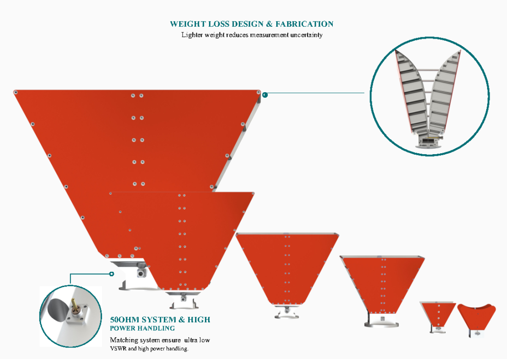
Over and above switches, RFecho manufactures a range of antennas that include horn antennas, log-periodic antennas, and omnidirectional antennas. Other passive devices include filters, attenuators, couplers, isolators, circulators, and the list is much longer.
All of our products can be customized based on frequency range, type of connector (SMA/N/N-Type/2.92mm), gain specification, environmental sealing needs (IP65/IP67), etc., so that they integrate seamlessly into your system design.
Do you want to create a new product line or modernize current infrastructure? RFecho has it all covered—from prototype to mass production.
FAQ
Q: What are the symptoms of my RF switch failure?
Some common symptoms are increased insertion loss, interference of isolation between ports, loss of signal, erratic switching behavior even under control voltages, or sudden heat generation during operation.
Q: Can I fix a malfunctioning RF switch on my own?
A: Most modern RF switches are sealed precision-made assemblies that are not meant to be user-repairable. Replacement is generally always superior to repairing unless it’s in some big modular assembly where components can be swapped out.
Q: What do I use to test an RF switch?
A: An S-parameter, such as return loss and isolation testing, would require a vector network analyzer (VNA) for testing. A multimeter can test for basic continuity, while an oscilloscope would be useful in confirming control signals.
Q: When should I keep my RF switches in shape?
A: Regular 6–12-month checks, depending on the usage environment, are advised—especially in outdoor or dusty conditions where connector contamination can occur faster.
Q: Does RFecho provide customized RF switch solutions?
A: Yes. RFecho specializes in providing customized solutions like custom port counts (SPnT), discrete frequency bands up to 67GHz+, special connector types like 2.4mm/K connectors, control interface options like TTL/USB/GPIB, and other ruggedization features according to client-specific requirements.
With RFecho as your reliable partner in RF technology—from switches to antennas—you enjoy engineering excellence with timely customer service and global delivery capability aligned to your project timelines.


 Typical Reasons RF Switches Fail
 Symptoms Suggesting Failure of an RF Switch
 What Makes RFecho’s RF Switches Reliable