Key Factors in Designing a High-Performance Microwave Antenna System
Introduction
Designing a microwave antenna system calls for a mix of basics like frequency handling and real-world tweaks for gain and stability. Microwave antennas work in ranges from GHz to THz, fitting uses in radar, telecom, and EMC testing. Directional types focus signals tightly, while omnidirectional ones spread them out. Key steps include balancing beamwidth with gain, picking the right polarization, and cutting side lobes. Lens antennas help focus waves sharply. Don’t forget sturdy builds against the weather and heat. Fine-tune with good matching and testing. This guide pulls from real antenna specs, like those with VSWR under 2 and gains up to 20 dBi, to show what works in practice.
Understanding Microwave Antenna Fundamentals
Microwave antennas handle radio waves at high frequencies. They send and receive signals in setups like radar or satellite links. What makes one a microwave antenna? It’s built for waves shorter than a meter, often in the GHz range. Think of them as tools that shape electromagnetic energy.
Frequencies matter a lot. Low end, say 0.1 GHz to 40 GHz, covers wireless testing and telecom. Higher, up to THz, hits advanced sensing. Applications vary: radar uses them for tracking, while EMC testing checks device interference. For instance, a broadband dual ridged horn antenna runs from 0.8 GHz to 18 GHz with gains from 5 to 14 dBi. That’s handy for 5G or satellite checks.
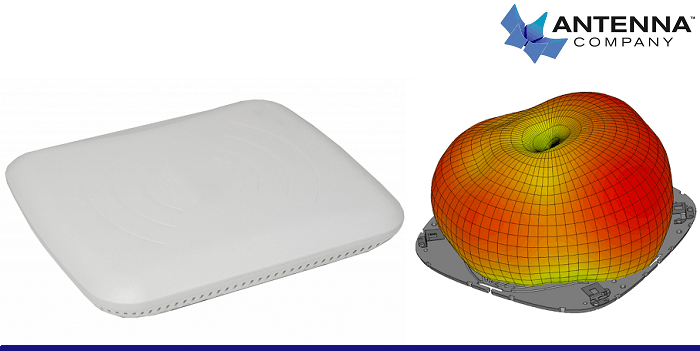
 Directional antennas point signals in one way, like a spotlight. Omnidirectional ones spread signals around, more like a bulb. Directional types suit long-distance links, cutting noise from the sides. Omnidirectional fit broadcast needs, covering all directions evenly. The difference shows in beam patterns; directional have narrow beams for focus, omnidirectional have wide ones for coverage. Sometimes you mix them in systems, but that’s a side note—most designs pick one based on the job.
Design Considerations for Directional Microwave Antennas
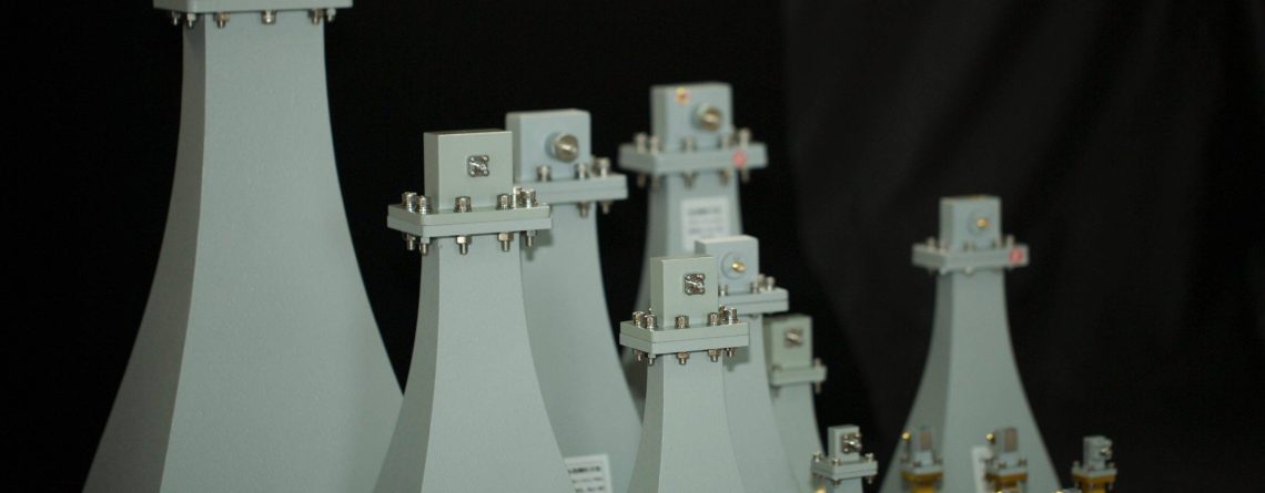
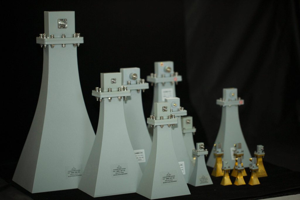
For directional antennas, trade-offs pop up between beamwidth and gain. A narrow beamwidth means higher gain, focusing power tightly. Wide beamwidth spreads it out, dropping gain. A 15 dBi gain horn at 1 GHz to 2 GHz, like one with a 2:1 VSWR max, shows this: it keeps steady gain across bands but limits the beam to useful spots.
Polarization counts too. Linear or circular? Alignment must match the sender and receiver. Miss it, and signals weaken. In practice, a horn with single linear polarization needs careful setup to avoid loss. Accuracy here prevents drops in field strength.
Side lobes cause trouble—they leak energy sideways, inviting interference. Minimize them with good shaping. A dual ridged horn at 18-40 GHz hits 20 dBi gain with a tylical VSWR, and its pattern has one main lobe, no big sides. Interference drops when lobes stay low, say under -20 dB. Real tests, like in EMC labs, prove this keeps signals clean.
 The Role of Microwave Lens Antennas
 The Role of Microwave Lens Antennas
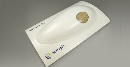
Lens antennas focus waves like optical lenses do light. The principle: vary the refractive index to bend rays to a point. Luneburg lenses, for example, use sphere symmetry for this, handling all polarizations.
Material picks affect efficiency. Dielectrics must handle low loss, keeping signals strong. A Luneburg lens from 1.7-2.6 GHz with 15 dBi gain and -20 dB return loss uses an all-dielectric build—light and cheap. Higher bands, like 30-40 GHz at 20.1 dBi, need materials that cut side lobes to -20 dB.
Integrate with feeds carefully. Mount on waveguides for seamless flow. A lens with an 8-degree beamwidth at 30 GHz pairs with standard interfaces. This setup boosts systems in sub-millimeter tests or satellite feeds. Oh, and while we’re on lenses, they shine in mobile setups where phase stays steady, but more on that later.
Structural and Environmental Factors
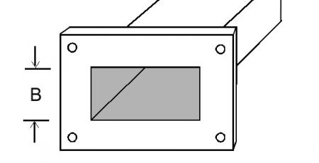
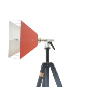
Stability starts with mechanics. Mounting must hold firm against vibrations. A lightweight horn at 0.62 kg, like one for 0.8-12 GHz, uses flanges or tripods for secure fits. Solutions include robust bases that bend under impact but snap back.
Weather hits hard. Seal for IP65 or better to block water. Materials like aluminum or copper resist corrosion. A conical horn with UG-385/U flange stands up in rain, keeping performance. Durability means powder coats or rubber paints—think biconical antennas tested for salt fog.
High-power systems heat up. Manage thermals with vents or materials that dissipate. A power-handling beast at 1500W max needs this to avoid warp. In radar, where 500W pulses run constantly, cooling keeps VSWR steady.
Performance Optimization Techniques
Match impedance to control VSWR. Aim for under 2:1 for low reflections. A probe antenna at 110-170 GHz hits 2:1 typical, ensuring clean signals. Bad match wastes power; good one boosts efficiency.
In mobile apps, the phase center must stay put. Shifts cause errors in tracking. Spiral antennas, like cavity-backed ones from 1-18 GHz, hold center with no offset, ideal for airborne use.
Calibrate and test thoroughly. Use standards like ANSI C63.5 for horns. Measure gain, VSWR, and patterns in labs. A dual ridged horn comes with data on these, input to systems for accuracy. Procedures include field tests for real-world tweaks.
Wrapping up, these factors build solid systems. From basics to fine details, like a 0.2-3 GHz antenna’s 6-15 dBi gain in EMC, it all ties back to practical specs. Miss one, and performance dips. But get them right? Systems run smoothly.
FAQ
Q:What frequency range should I pick for radar applications?
A:Radar often uses 1-18 GHz or higher, like X-band, for weather. A dual ridged horn from 1-18 GHz with 7-14 dBi gain works well for military or airborne setups.
Q:How do I reduce interference in directional antennas?
A:Cut side lobes below -20 dB. Designs with single main lobes, such as 18-40 GHz horns, help. Align polarization, too.
Q:Are lens antennas good for high-power?
A:Yes, but watch materials. A 30-40 GHz Luneburg handles it with low loss, giving 20 dBi gain.
Q:What’s the big deal with VSWR?
A:Under 2:1 means less signal bounce. High VSWR wastes energy; aim for 1.5:1 like in many broadband horns.
Q:How to test antenna stability in bad weather?
A:Lab checks for IP65, plus field trials. Lightweight builds with rubber coats hold up in wind and rain.