15–25 GHz Four-Channel Receiver IC – MH214W


LO input frequency: 7.5 to 12.5 GHz
Noise figure: 2 to 11 dB
Minimum gain: 32 dB typ.
Gain control range: 20 dB typ.
Supply voltage: 1.1 V, 3.3 V
Four integrated receive channels
12-bit ADC
- Description
- Datasheet
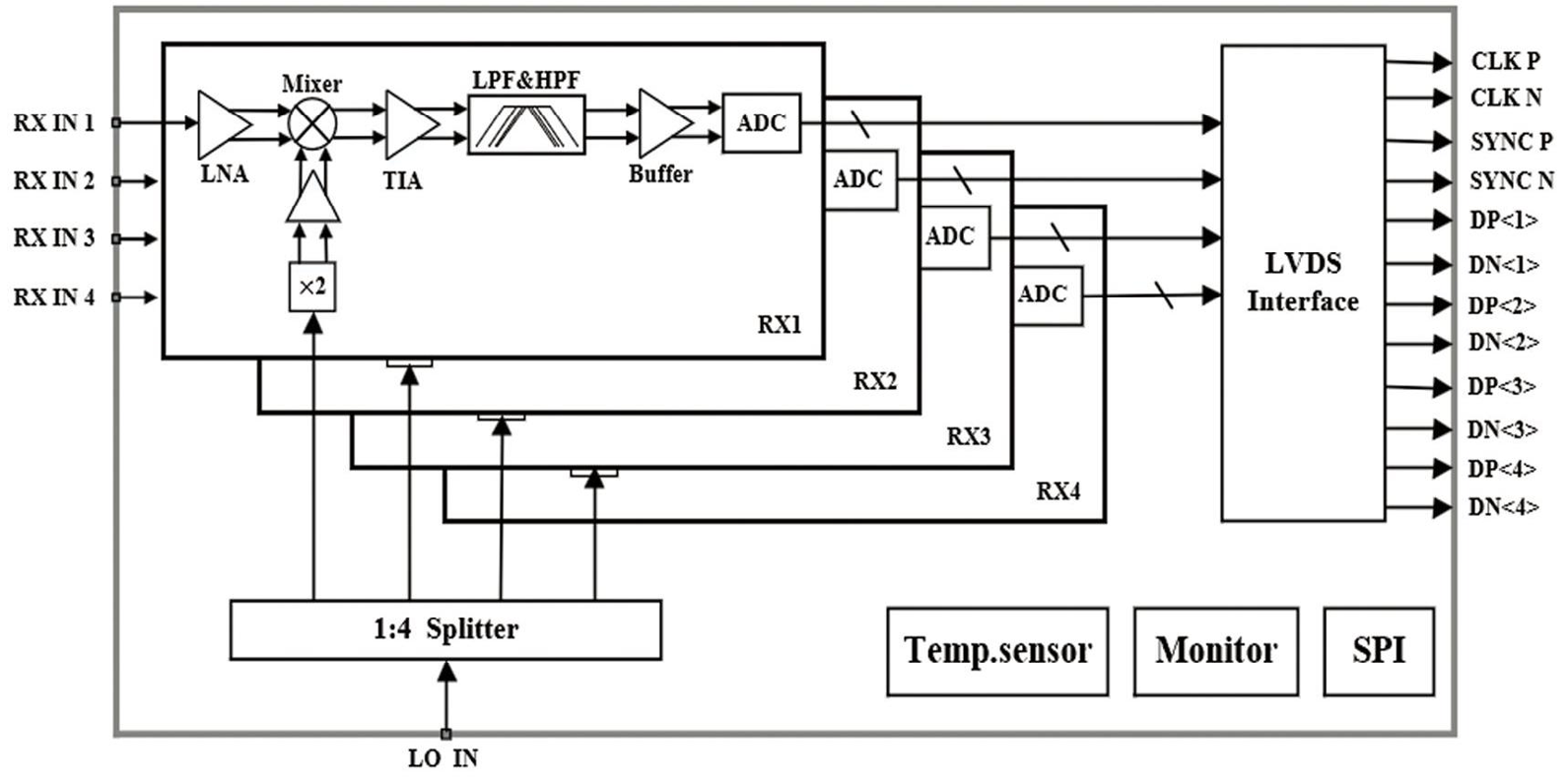
- Functional Block Diagram
Description
The MH214W is a four-channel receiver IC covering 15–25 GHz. It integrates four receive front-ends, analog baseband circuitry, ADCs, an LVDS interface, an on-chip temperature sensor, fault monitoring and SPI control. Four channels receive, digitize and transfer signals simultaneously. SPI controls operating state and channel switching; LVDS carries the ADC data.
Applications: Millimeter-wave security screening, traffic radar, industrial monitoring and fire safety.
Product status: Engineering sample.
Four-Channel Receiver IC Specifications | |
| 15–25 GHz | |
| MH214W | |
Index | Value |
| RX input frequency | 15 to 25 GHz |
| LO input frequency | 7.5 to 12.5 GHz |
| Noise figure | 2 to 11 dB; 11 dB at minimum gain; 4 dB at maximum gain |
| Input 1 dB compression point | -20 dBm typ.; At minimum gain |
| Minimum gain | 32 dB typ. |
| Gain control range | 20 dB typ. |
| IF bandwidth | 0.5 to 50 MHz |
| LO input power | −20 dBm typ. |
| RX gain variation with frequency | −1.5 to +1.5 dB |
| RX gain variation with temperature | −1.5 to +1.5 dB |
| Channel-to-channel gain variation | −1.5 to +1.5 dB |
| Channel-to-channel phase variation | −7 to +7 ° |
| Channel isolation | 40 dB typ. |
| Power-down recovery time | 250 μs typ. |
| Supply voltage | 1.1 V, 3.3 V |
| Package / dimensions | 6.55 × 5.55 mm |
Features | |
| Four integrated receive channels | |
| 12-bit ADC | |
| SPI control and LVDS data interfaces | |
| Integrated temperature sensor and fault monitoring | |
| Power consumption: 880 mW, four channels, continuous wave | |
| ADC sampling rate: 100 MSPS maximum | |
Application Scenarios




Functional Block Diagram