Is the Gain of antenna same as an amplifier
Gain of antenna
Another useful measure describing the performance of an antenna is the gain. Although
the gain of the antenna is closely related to the directivity, it is a measure that takes into
account the efficiency of the antenna as well as its directional capabilities.
Gain of an antenna (in a given direction) is defined as “the ratio of the intensity, in
a given direction, to the radiation intensity that would be obtained if the power accepted
by the antenna were radiated isotropically. The radiation intensity corresponding to the
isotropically radiated power is equal to the power accepted (input) by the antenna divided
by 4π.”
In most cases we deal with relative gain, which is defined as “the ratio of the power
gain in a given direction to the power gain of a reference antenna in its referenced
direction.” The power input must be the same for both antennas. The reference antenna
is usually a dipole, horn, or any other antenna whose gain can be calculated or it is
known. In most cases, however, the reference antenna is a lossless isotropic source.
Thus
![]()
When the direction is not stated, the power gain is usually taken in the direction of
maximum radiation.
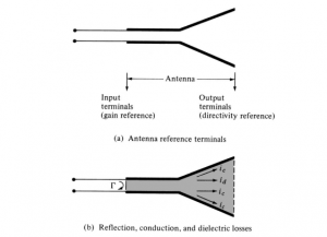
Referring to Figure 1.14(a), we can write that the total radiated power (P rad) is related
to the total input power (P in) by
![]()
where ecd is the antenna radiation efficiency (dimensionless), which is defined in
Eqs. (1.22) and (1.23). According to the IEEE Standards, “gain does not include losses
arising from impedance mismatches (reflection losses) and polarization mismatches
(losses).”
Here we define two gains: one, referred to as gain (G), and the other, referred to as
absolute gain (G abs), that also takes into account the reflection/mismatch losses represented in both Eqs. (1.22) and (1.23).
Using Eq. (1.25) reduces Eq. (1.24) to
![]()
which is related to the directivity of Eq. (1.9) by
G(θ, φ) = ecdD(θ, φ) (1.27)
In a similar manner, the maximum value of the gain is related to the maximum directivity
of Eq. (1.9a) and (1.12) by
G0 = G(θ, φ)|max = ecdD(θ, φ)|max = ecdD0 (1.27a)
While Eq. (1.25) does take into account the losses of the antenna element itself,
it does not take into account the losses when the antenna element is connected to a
transmission line, as shown in Figure 1.14. These connection losses are usually referred
to as reflections (mismatch) losses, and they are taken into account by introducing a
reflection (mismatch) efficiency er, which is related to the reflection coefficient as shown
1.9 GAIN 25
in Eq. (1.23) or er = (1 – ||2). Thus we can introduce an absolute gain G abs that takes
into account the reflection/mismatch losses (due to the connection of the antenna element
to the transmission line), and it can be written
Gabs(θ, φ) = erG(θ, φ) = (1 – ||2)G(θ, φ)
= erecdD(θ, φ) = eoD(θ, φ) (1.28)
where eo is the overall efficiency as defined in Eqs. (1.22) and (1.23). Similarly, the
maximum absolute gain G 0abs of Eq. (1.28) is related to the maximum directivity
D 0 by
G0abs = Gabs(θ, φ)|max = erG(θ, φ)|max = (1 – ||2)G(θ, φ)|max
= erecdD(θ, φ)|max = eoD(θ, φ)|max = eoD0 (1.28a)
If the antenna is matched to the transmission line, that is, the antenna input impedance
Z in is equal to the characteristic impedance Z 0 of the line (|| = 0), then the two gains
are equal (G abs = G).
As was done with the directivity, we can define the partial gain of an antenna for
a given polarization in a given direction as “that part of the radiation intensity corresponding to a given polarization divided by the total radiation intensity that would be
obtained if the power accepted by the antenna were radiated isotropically.” With this
definition for the partial gain, then, in a given direction, “the total gain is the sum of the
partial gains for any two orthogonal polarizations.” For a spherical coordinate system,
the total maximum gain G 0 for the orthogonal θ and φ components of an antenna can
be written, in a similar form as was the maximum directivity in Eqs. (1.10), (1.10a) and
(1.10b), as
| G0 = Gθ + Gφ | (1.29) |
| while the partial gains Gθ and Gφ are expressed as |
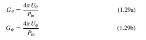
where
U θ = radiation intensity in a given direction contained in E θ field component
U φ = radiation intensity in a given direction contained in E φ field component
P in = total input (accepted) power
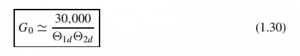
For many practical antennas an approximate formula for the gain, corresponding to
Eq. (1.14) or (1.14a) for the directivity, is
In practice, whenever the term “gain” is used, it usually refers to the maximum gain
as defined by Eq. (1.27a) or (1.28a).
Usually the gain is given in terms of decibels instead of the dimensionless quantity
of Eq. (1.27a). The conversion formula is given by
G0(dB) = 10 log10[ecdD0 (dimensionless)] (1.31)
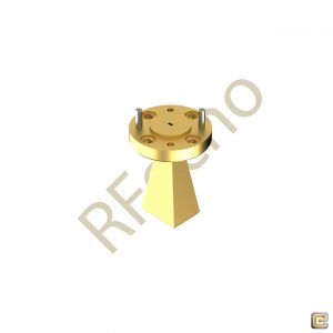
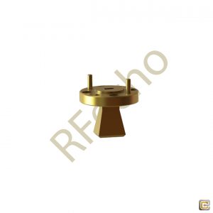
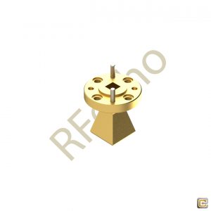
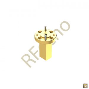
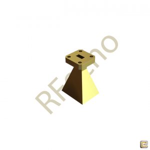
Millimeter SGH Antenna
Showing 1–16 of 41 results
-
ADAS, Antenna, Antenna Array, Application, Gain Measurement Systems, Millimeter SGH Antenna, National Safety, Point to Point Radio, Radar, Radio Communication TX/RX, Satcom, Telecom, Testing & Measurement
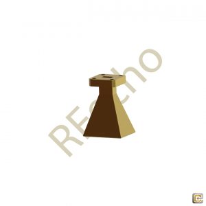
10 dBi Gain, 110 GHz to 170 GHz, WR-06 Waveguide Millimeter SGH Antenna
-
ADAS, Antenna, Antenna Array, Application, Gain Measurement Systems, Millimeter SGH Antenna, National Safety, Point to Point Radio, Radar, Radio Communication TX/RX, Satcom, Telecom, Testing & Measurement
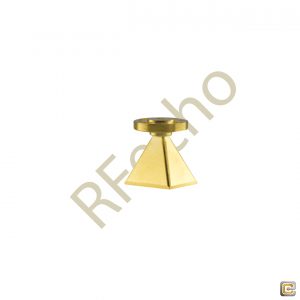
10 dBi Gain, 26.5 GHz to 40 GHz, WR-28 Waveguide Millimeter SGH Antenna
-
ADAS, Antenna, Antenna Array, Application, Gain Measurement Systems, Millimeter SGH Antenna, National Safety, Point to Point Radio, Radar, Radio Communication TX/RX, Satcom, Telecom, Testing & Measurement
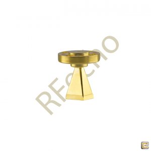
10 dBi Gain, 40 GHz to 60 GHz, WR-19 Waveguide Millimeter SGH Antenna
-
ADAS, Antenna, Antenna Array, Application, Gain Measurement Systems, Millimeter SGH Antenna, National Safety, Point to Point Radio, Radar, Radio Communication TX/RX, Satcom, Telecom, Testing & Measurement
10 dBi Gain, 60 GHz to 90 GHz, WR-12 Waveguide Millimeter SGH Antenna
-
ADAS, Antenna, Antenna Array, Application, Gain Measurement Systems, Millimeter SGH Antenna, National Safety, Point to Point Radio, Radar, Radio Communication TX/RX, Satcom, Telecom, Testing & Measurement
13 dBi Gain, 60 GHz to 90 GHz, WR-12 Waveguide Millimeter SGH Antenna
-
ADAS, Antenna, Antenna Array, Application, Gain Measurement Systems, Millimeter SGH Antenna, National Safety, Point to Point Radio, Radar, Radio Communication TX/RX, Satcom, Telecom, Testing & Measurement
15 dBi Gain, 40 GHz to 60 GHz, WR-19 Waveguide Millimeter SGH Antenna

-
ADAS, Antenna, Antenna Array, Application, Gain Measurement Systems, Millimeter SGH Antenna, National Safety, Point to Point Radio, Radar, Radio Communication TX/RX, Satcom, Telecom, Testing & Measurement
15 dBi Gain, 50 GHz to 75 GHz, WR-15 Waveguide Millimeter SGH Antenna
-
ADAS, Antenna, Antenna Array, Application, Gain Measurement Systems, Millimeter SGH Antenna, National Safety, Point to Point Radio, Radar, Radio Communication TX/RX, Satcom, Telecom, Testing & Measurement
15 dBi Gain, 60 GHz to 90 GHz, WR-12 Waveguide Millimeter SGH Antenna

-
ADAS, Antenna, Antenna Array, Application, Gain Measurement Systems, Millimeter SGH Antenna, National Safety, Point to Point Radio, Radar, Radio Communication TX/RX, Satcom, Telecom, Testing & Measurement
15 dBi Gain, 75 GHz to 110 GHz, WR-10 Waveguide Millimeter SGH Antenna
-
ADAS, Antenna, Antenna Array, Application, Gain Measurement Systems, Millimeter SGH Antenna, National Safety, Point to Point Radio, Radar, Radio Communication TX/RX, Satcom, Telecom, Testing & Measurement
17 dBi Gain, 26.5 GHz to 40 GHz, WR-28 Waveguide Millimeter SGH Antenna
-
ADAS, Antenna, Antenna Array, Application, Gain Measurement Systems, Millimeter SGH Antenna, National Safety, Point to Point Radio, Radar, Radio Communication TX/RX, Satcom, Telecom, Testing & Measurement
17 dBi Gain, 40 GHz to 60 GHz, WR-19 Waveguide Millimeter SGH Antenna
-
ADAS, Antenna, Antenna Array, Application, Gain Measurement Systems, Millimeter SGH Antenna, National Safety, Point to Point Radio, Radar, Radio Communication TX/RX, Satcom, Telecom, Testing & Measurement
17 dBi Gain, 50 GHz to 75 GHz, WR-15 Waveguide Millimeter SGH Antenna

-
ADAS, Antenna, Antenna Array, Application, Gain Measurement Systems, Millimeter SGH Antenna, National Safety, Point to Point Radio, Radar, Radio Communication TX/RX, Satcom, Telecom, Testing & Measurement
20 dBi Gain, 110 GHz to 170 GHz, WR-06 Waveguide Millimeter SGH Antenna