


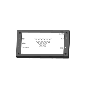
QSF-2500D High-Voltage-Output Power Modules


The QSF-2500D power module family is described by the configuration-specific ratings in the following tables. DC/DC isolated conversion. Maximum output power: 2500W. Input undervoltage protection. Refer to the selection table, pin assignments and application guidance for the selected configuration.
Ratings apply to the selected configuration. See the datasheet for test conditions and model designation notes.
Request a Quote
- Description
- Technical Data
- Datasheet
- OUTLINE
- Reviews (0)
QSF-2500D High-Voltage-Output Power Modules
The QSF-2500D power module family is described by the configuration-specific ratings in the following tables. DC/DC isolated conversion. Maximum output power: 2500W. Input undervoltage protection. Refer to the selection table, pin assignments and application guidance for the selected configuration.
- DC/DC isolated conversion
- Maximum output power: 2500W
- Input undervoltage protection
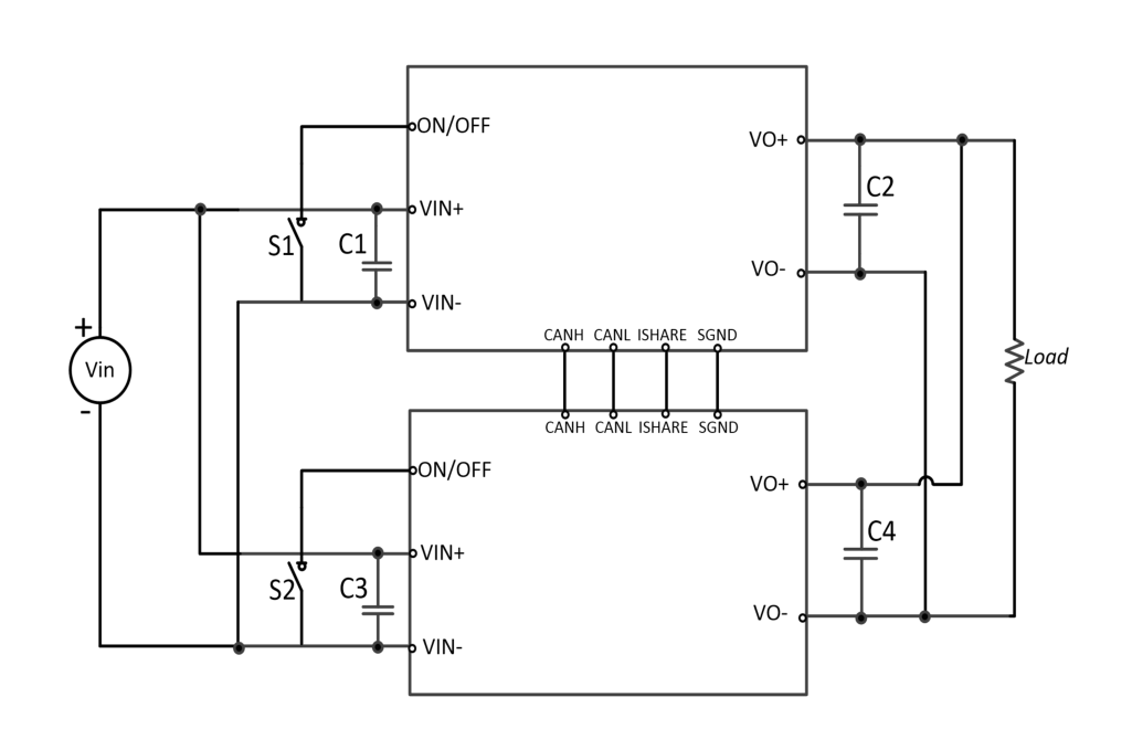
- Output overvoltage, overcurrent, short circuit, Overtemperature protection; parallel operation
- Operating temperature (Tc): -55°C to 105°C
- Storage temperature: -55°C to 125°C
Product Selection
| Model | Input voltage (V) | Output voltage (V) | Output current (A) | Efficiency (%) half load / full load | Capacitive load (µF) max. | Ripple (mV) Typical |
|---|---|---|---|---|---|---|
| QSF2500D-400S350NNM | 270 to 500 | 350 | 7.14 | 94/93.5 | 5000 | 2500 |
Technical Data — QSF-2500D
| Characteristic | Test temperature | Min. | Typ. | Max. | Unit | Conditions |
|---|---|---|---|---|---|---|
| Input voltage range | Room, High, Low | 270 | 400 | 500 | V | full load range, 270V input, limited by duty cycle, output at full load is 346V approximately, normal operating range: 280V to 500V |
| Input surge voltage | Room | — | — | 520 | V | t=100ms, full load |
| No-load power consumption | Room | — | 10 | — | W | rated input voltage, no output load |
| Output voltage adjustment range | Room | 80 | — | 110 | %VO | rated input voltage, IO≤ maximum value and PO≤VO×IOmax |
| Line regulation | Room | -1 | — | +1 | %VO | Input voltage 280V to 500V, full load |
| Load regulation | Room, High, Low | -1 | — | +1 | %VO | rated input voltage, full load range |
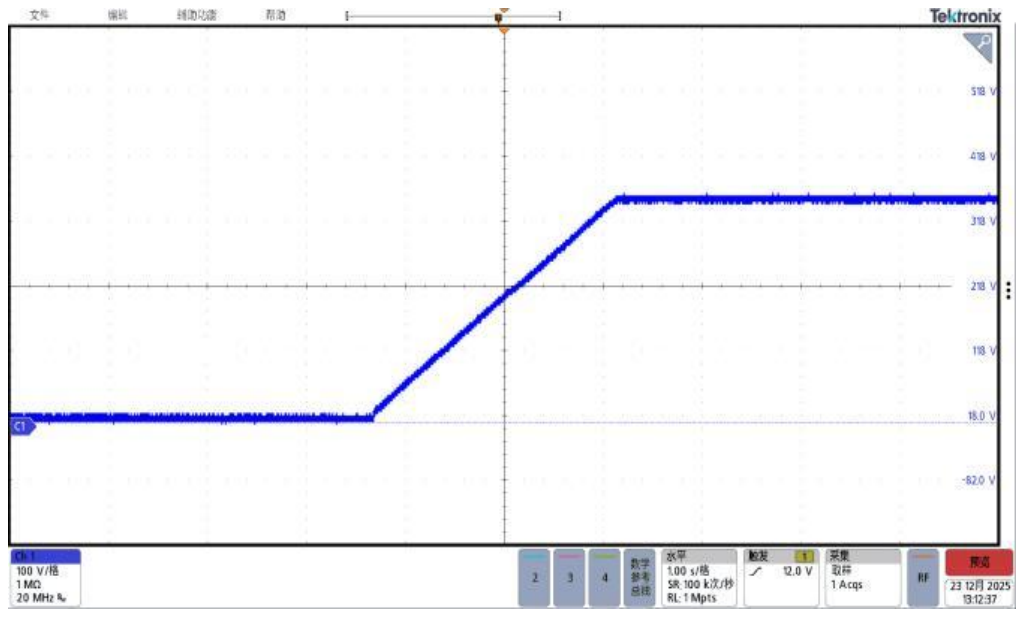
| Turn-on delay a | Room | — | 1.7 | — | s | time from power-on until output voltage reaches 10% time |
| Output voltage rise time a | Room | — | 2.3 | — | s | output voltage from 10% rises to 90% time |
| Enable turn-on delay a | Room | — | 0.5 | — | s | time from enable assertion until output voltage reaches 10% time |
| Enable logic level (negative logic) | Room | 0 | — | 0.7 | V | output enabled when grounded or low, see the application guide for control methods |
| Enable logic level (negative logic) | Room | 3.5 | — | 12.0 | V | no output when high or open, see the application guide for control methods |
| Enable logic level (positive logic) | Room | 0 | — | 0.7 | V | no output when grounded or low, see the application guide for control methods |
| Enable logic level (positive logic) | Room | 3.5 | — | 12.0 | V | output enabled when high or open, see the application guide for control methods |
| Input undervoltage protection | Room | 250 | — | 265 | V | half load |
| Output overcurrent protection | Room | 7.3 | — | — | A | hiccup mode (load CC mode), automatic recovery |
| Output short-circuit protection | Room | — | — | — | — | hiccup mode, automatic recovery |
| Output overvoltage protection | Room | 115 | — | 130 | %VO | hiccup mode, automatic recovery |
| Switching frequency | Room | — | 100 | — | kHz | |
| Isolation withstand voltage | Room | - | — | no breakdown, no flashover; input to output, 1500Vac/60s/<3.5mA | ||
| Insulation resistance | Room | 100 | — | — | MΩ | 500Vdc, input, output, between each pair of terminals and case |
| Weight | / | — | 320 | — | g |
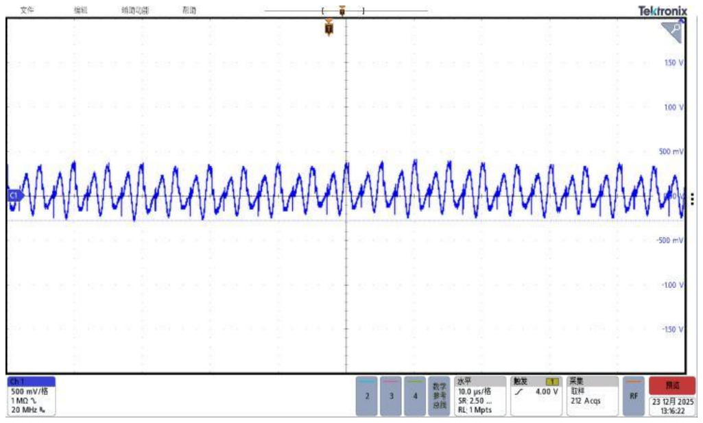
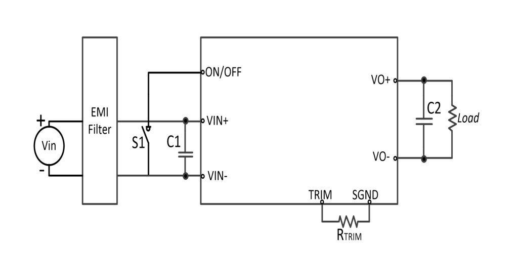
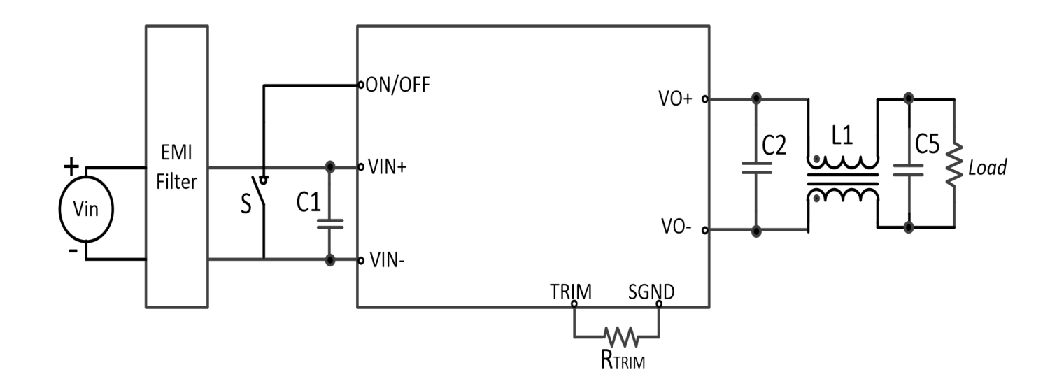
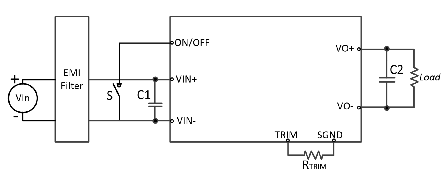
Note: 1, for other package types or temperature-screening grades, use the corresponding model designation rules when ordering, contact technical support for details; 2, electrical data and mechanical dimensions in this manual are for product selection reference, the detailed product specification governs the final requirements; 3, see the typical application circuit for the ripple measurement method.
a: typical model QSF2500D-400S350NNM time, values may differ for other models, contact technical support for details.
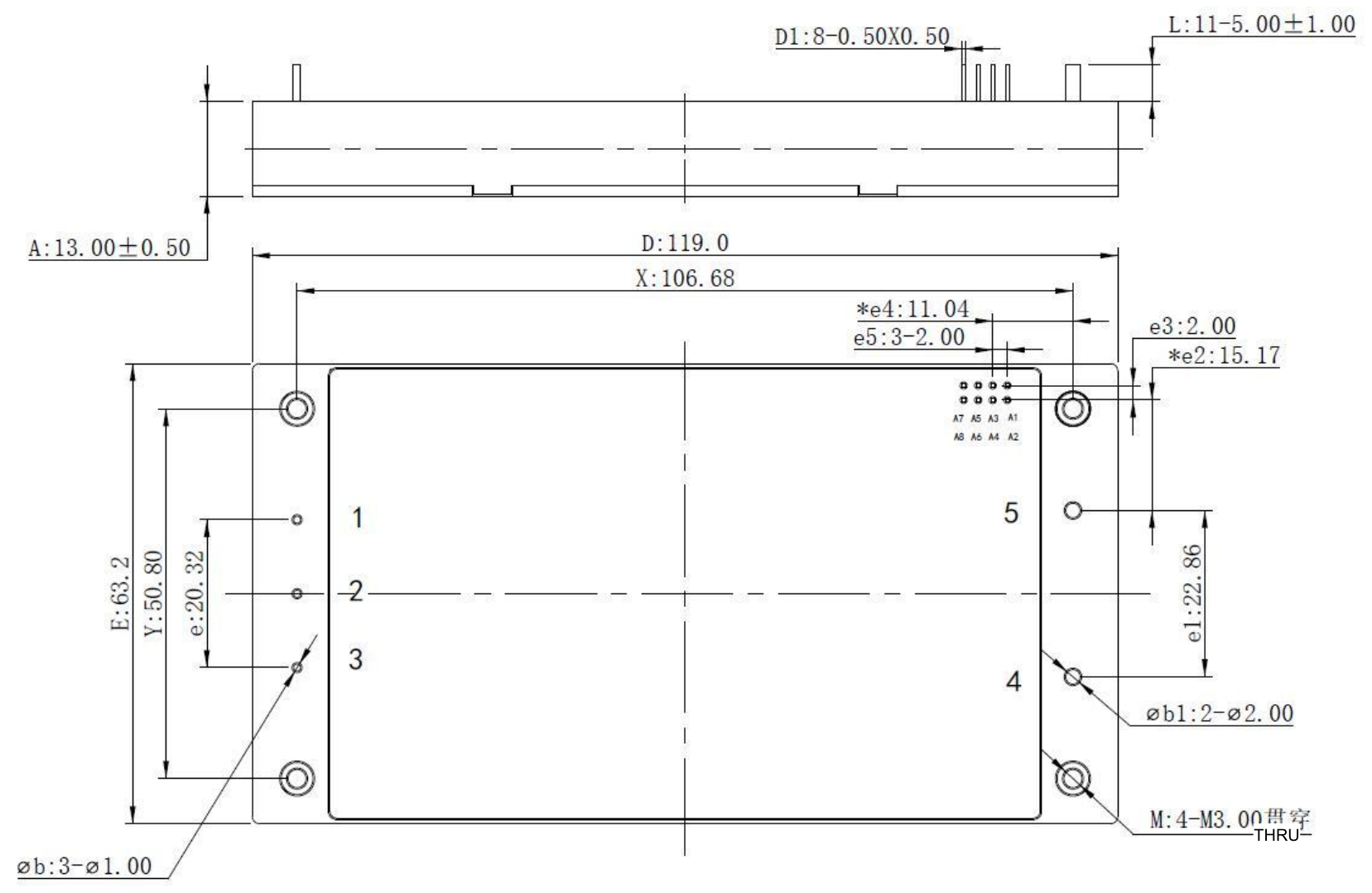
Module dimensions are shown below, for dimensions without an explicit tolerance, for dimensions specified in X.X format, the dimensional tolerance is ±0.5mm; dimensions specified in X.XX format, the dimensional tolerance is ±0.25mm.
Outline & Mechanical Dimensions
Reviews
There are no reviews yet.