


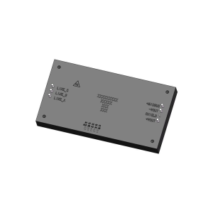
Three-phase PFC Power module


The Three-Phase PFC power factor correction module family is described by the configuration-specific ratings in the following tables. Three-phase 115Vrms AC/DC power factor correction. Maximum output power: 2000W. 45 to 800Hz Wide input-frequency range. Refer to the selection table, pin assignments and application guidance for the selected configuration.
Ratings apply to the selected configuration. See the datasheet for test conditions and model designation notes.
Request a Quote
- Description
- Technical Data
- Datasheet
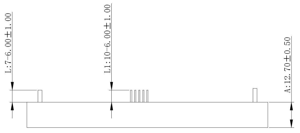
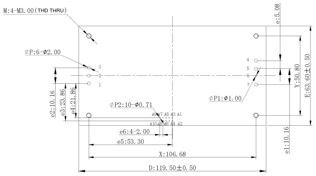
- OUTLINE
- Reviews (0)
Three-phase PFC Power module
The Three-Phase PFC power factor correction module family is described by the configuration-specific ratings in the following tables. Three-phase 115Vrms AC/DC power factor correction. Maximum output power: 2000W. 45 to 800Hz Wide input-frequency range. Refer to the selection table, pin assignments and application guidance for the selected configuration.
- Three-phase 115Vrms AC/DC power factor correction
- Maximum output power: 2000W
- 45 to 800Hz Wide input-frequency range
- Input undervoltage, overvoltage, Overtemperature protection
- Operating temperature (Tc): -55°C to 105°C
- Storage temperature: -55°C to 125°C
Product Selection
| Model | Input voltage (Vac) | Output voltage (Vdc) | Output current (A) | Efficiency (%) half load / full load | Ripple (V) Typical |
|---|---|---|---|---|---|
| QFCF2K0-115S270NNM | 85 to 140 | 275 | 7.4 | 94/95 | 2 |
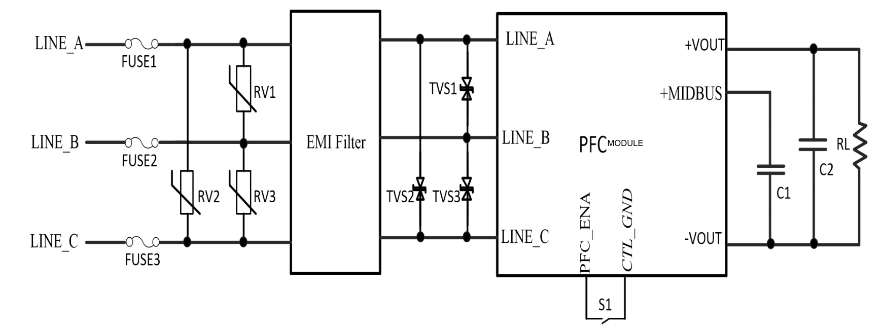
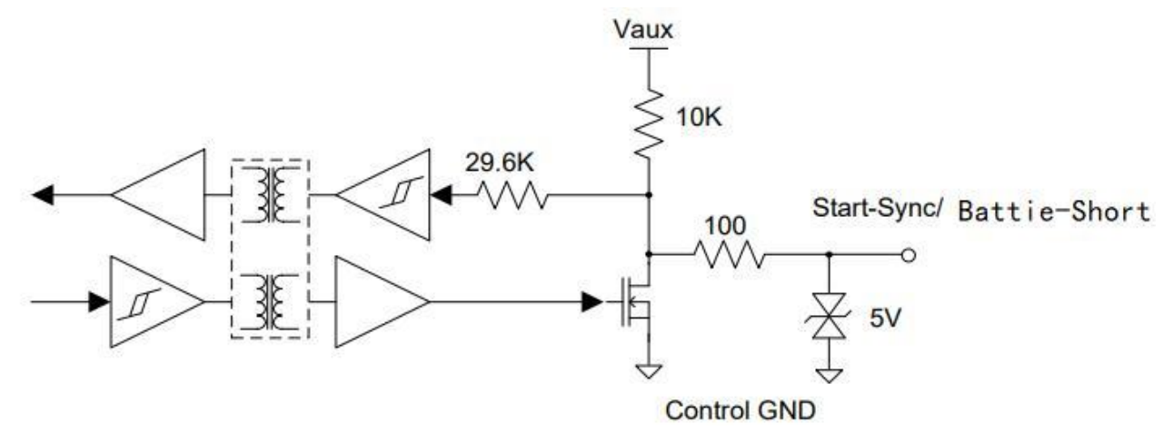
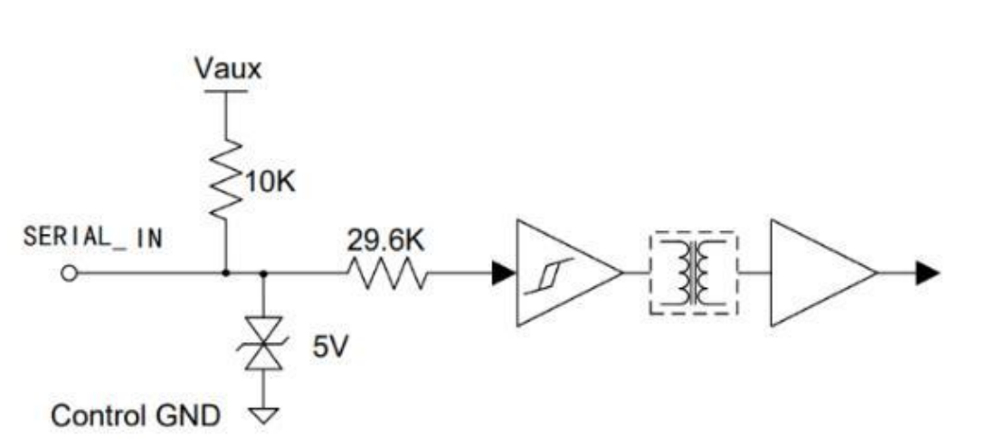
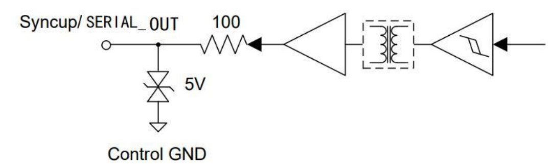
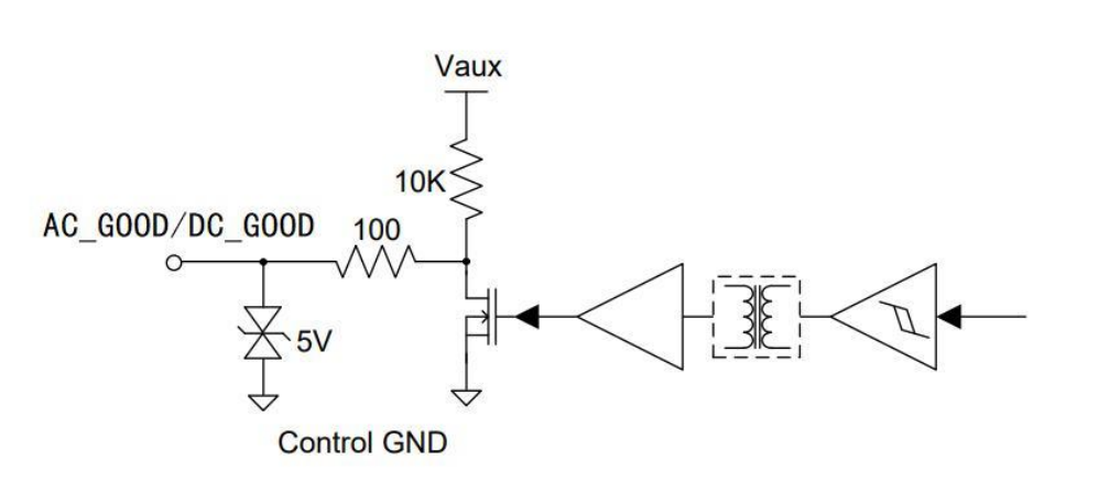
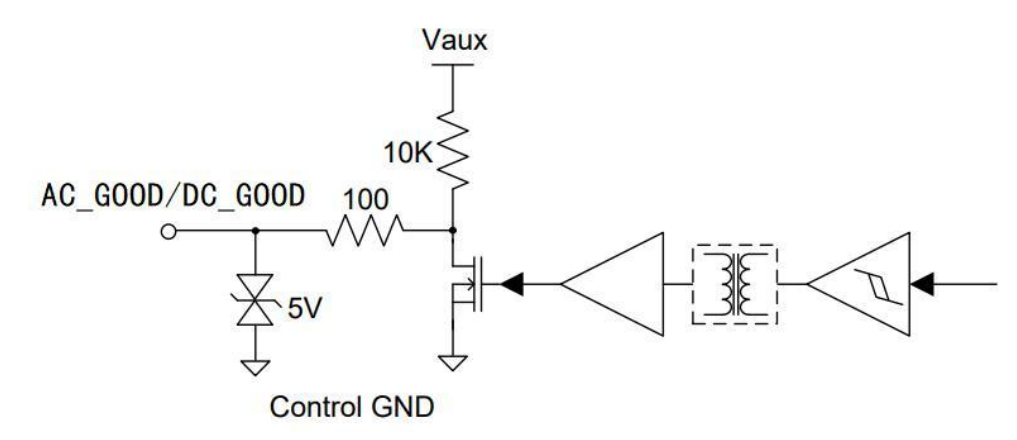
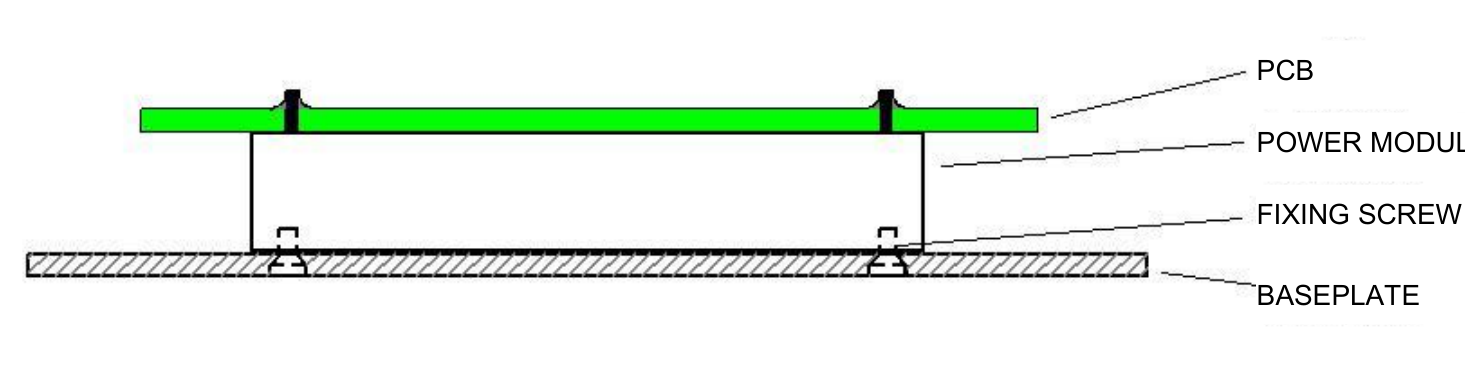
Technical Data — Three Phase PFC
| Characteristic | Test temperature | Min. | Typ. | Max. | Unit | Conditions |
|---|---|---|---|---|---|---|
| Input voltage range | Room, High, Low | 85 | 115 | 140 | Vac | full load range, phase voltage |
| Maximum input current | Room, High, Low | — | — | 7.5 | Arms | full load range |
| Input frequency range | Room | 47 | 50 | 800 | Hz | full input-voltage range, full load range |
| Power factor | Room | 0.97 | 0.99 | — | — | full load, 400Hz |
| Input current total harmonic distortion | Room | — | — | 3.0 | % | full load |
| No-load power consumption | Room | — | 7.5 | — | W | no load, enabling |
| Standby power consumption | Room | — | 6.5 | — | W | disabling |
| line-imbalance protection | Room | — | 35 | — | Vac | amplitude |
| line-imbalance protection | Room | — | 15 | — | deg | phase |
| Input undervoltage protection | Room | — | 65 | — | Vac | duration 150ms |
| Input overvoltage protection | Room | — | 150 | — | Vac | duration 1s |
| Output overvoltage protection | Room | 300 | 310 | 320 | Vdc | |
| Enable turn-on delay | Room | — | 150 | 300 | ms | full input-voltage range |
| Start-up delay | Room | — | 190 | 380 | ms | full input-voltage range |
| Output voltage; +VOUT | Room, High, Low | 270 | 275 | 280 | V | rated input voltage, no load |
| Output voltage; +VOUT | Room, High, Low | 248 | 265 | 278 | V | full input-voltage range, 0A<IO≤7.4A |
| Output voltage; +MIDBUS | Room, High, Low | 145 | 200 | 230 | V | full input-voltage range, full load range |
| Output current; +VOUT | Room, High, Low | — | — | 7.4 | A | 100Vac to 140Vac |
| Output current; +VOUT | Room, High, Low | — | — | 6.1 | A | 85Vac to 100Vac |
| Output current; +MIDBUS | Room, High, Low | — | — | 10 | A | full input-voltage range |
| Recommended External Capacitor Values | Room | 100 | 220 | 5000 | µF | full input-voltage range, full load range |
| Efficiency; +VOUT | Room | 92 | 95 | — | % | full load |
| Efficiency; +MIDBUS | Room | 93 | 96 | — | % | full load |
| Output voltage ripple | Room | — | 2 | — | V | peak-to-peak, 20MHz, 115V/400Hz, full load, output capacitor 120µF |
| AC input status indication AC GOOD (Output signal) | Room, High, Low | — | 3.3 | — | V | system normal: logic high |
| AC input status indication AC GOOD (Output signal) | Room, High, Low | — | — | 0.4 | V | system fault: logic low |
| DC output status indication DC GOOD (Output signal) | Room, High, Low | — | 3.3 | — | V | system normal: logic high |
| DC output status indication DC GOOD (Output signal) | Room, High, Low | — | — | 0.4 | V | system fault: logic low |
| PFC enable PFC ENA (Input signal: negative logic) | Room, High, Low | — | — | 0.8 | V | Turn-on voltage |
| PFC enable PFC ENA (Input signal: negative logic) | Room, High, Low | 3.3 | — | — | V | Turn-off voltage |
| auxiliary supply 3.3V AUX | Room, High, Low | 3.19 | 3.30 | 3.43 | V | Voltage |
| auxiliary supply 3.3V AUX | Room, High, Low | — | — | 100 | mA | Current |
| Switching frequency | Room, High, Low | — | 200 | — | kHz | |
| Dielectric withstand voltage | Room | - | no breakdown, no flashover; pin 1 to 7 to case: 2150Vdc, 1min, slew rate 200Vac/s, leakage current less than 3.5mA; pin 1 to 7 for signal pins: 1000Vdc, 1min, slew rate 200Vdc/s, leakage current less than 3.5mA; | |||
| Insulation resistance | Room | 100 | — | — | MΩ | pin 1 to 7 to case, Signal pin, 500Vdc |
| Weight | / | — | 298 | — | g |
Outline & Mechanical Dimensions
Reviews
There are no reviews yet.