What Differents The Broadband Composite Structure SpiralAntenna With A Ladder-Shaped Backed-Cavity With The Traditional Backed-Cavity
What Differents The Broadband Composite Structure SpiralAntenna With A Ladder-Shaped Backed-Cavity With The Traditional Backed-Cavity
Abstract
A particular backed-cavity with a hybridstructure is proposed for a broadband composite structurespiral antenna. And the antenna is feed by an ultra wide-band balun. This cavity makes the spiral antenna workoperate from 400MHz to 4GHz and without the lossintroduced by absorbing materials that are usedconventionally to broadband spirals. Additionally, thecavity also contribute to the unidirectional radiation ofmicrowave. Based on the reflex and superpositioncharacteristic of microwave, a ladder liked metallic body isplaced in the internal space of backed-cavity to improvethe gain at the most part ofthe frequency range. Accordingto the simulated results, the antenna performances areeffectively improved by using this backed-cavity.
Keywords- broadband, ultra wide-band balun, compositestructure spiral antenna, backed-cavity. Archimedes Spiral Antenna. circular polarization. LHCP, RHCP. low-profile antenna .
I. INTRODUCTION
Since their introduction in the mid-1960s spiralantennas have emerged as leading candidates for variouscommercial and military applications requiringbroadband circularly polarised operation. And a spiralantenna isolated in free space operates as a widebandantenna that radiates a bi-directional circularly polarizedbeam. In order to eliminate the backward radiation as faras possible in conventional spiral antenna design,absorbing materials is mainly used for obtainunidirectional beam. In that case, it is hard to makeeffective use of the backward radiate waves. At the sametime, it leads to a loss of half radiation energy andrestriction of antenna gain.
Recently, a metallic backedcavity placed at quarterwavelength position is commonly used to obtainunidirectional beam. However, The fixed physical lengthleads to destructive interferences between direct andreflected waves from metallic backed-cavity in mostfrequency region. Therefore, the broadband characteristicof spiral antenna is seriously limited and deteriorate.
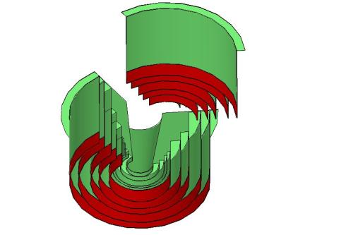
To mitigate this deterioration, a ladder liked metallicreflector with particular structure baced on reflex andsuperposition characteristic of microwave is introducedto take full advantage of backward radiation. Its physicallength is not fixed. The reflecting surface is of a ladderliked distribution. With the growth of antenna radius,each ladder turns more and more deep in order to keep aquarter wavelength position.When the waves from oneside of antenna travel to the reflector, the surface ofcavity which gradually changes with antenna radius andtransforms the bi-directional beam into a unidirectionalbeam makes the reflected waves from metallic surface ofbacked-cavity and forward radiate waves from antennasurface at each frequency (from 400MHz to 4GHz)added together without phase differences.
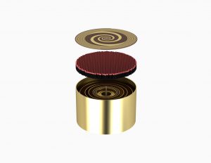
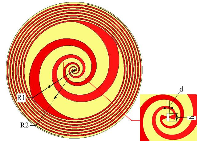
RFecho also gives a kind of composite structurespiral antenna which is a distorted form of traditionalspiral antenna. The antenna is composed of equiangularspiral and Archimedean spiral, that the initial part usesequiangular spiral and the terminal part usesArchimedean spiral. This structure can reduce thereflection of the current in terminal of spiral antenna, soas to improve the performance of equiangular spiral atlow frequency region. Meanwhile it has overcome theshortcomings that great transmission loss and lowefficiency with Archimedean spiral.
II.COMPOSITESPIRALANTENNADESIGNWITHLADDER-SHAPEDBACKED-CAVITY
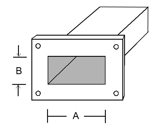
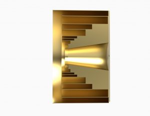
In order to demonstrate our design on the spiralantenna with ladder-shaped backed-cavity, a compositestructure spiral antenna with frequency range of400MHz~4GHz is introduced for reference firstly. Theradius of equiangular spiral , and the radius of the wholeantenna . The width and spacing between Archimedeanspiral arms , the substrate thickness , the distancebetween two feeding point , and the permittivity ofsubstrate is 4.4 (FR4_epoxy substrate materials). Thecomposite structure spiral antenna is shown in Fig.1. Thespiral antenna with a same amplitude-phase balance feeduses an ultra wide-band balun to feed itself. The length of balun , width , thickness. The positive microstrip patch(red) has two terminal widths and . The oppositemicrostrip patch(blue) has two terminal widths and .combine with balun.
As to the specific dimensions of metal reflector,it is indicated in Fig.2. In Fig.3. the internal structure of
special-shaped metallic backed-cavity is illustrated.
III.SIMULATEDRESULTSOFANTENNNA
The VSWR curve of ladder shaped backed-cavityspiral antenna is indicated that VSWR is less than 2.0 inthe operational frequency band. It is important that ring-shaped slot paly an significant role in decreasing VSWR,especially the absorbing material using on the top of thering part. As is shown in Fig.4, the axial ratio curve ofbacked-cavity spiral antenna at five frequency points is given.
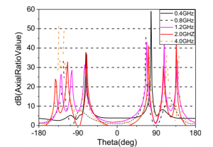
From Fig.4, we can see that all five frequency points sampled from 400MHz to 4GHz are inferior to 5. It
illustrates that the antenna shows stable and excellent characteristics of circular polarization during operationa frequency region. Additionally, we have simulated the ladder-shaped backed-cavity spiral antenna and obtained far field radiation pattern of antenna at five frequency points, which are sampled from operational frequency region to manifest the gain of spiral antenna with laddershaped backed-cavity.
Radiation Gain Of Spiral Antenna With Ladder-shped Cavity
| Frequency | 400MHz | 800MHz | 1.2GHz | 2GHz | 4GHz |
| Gain | 3.4dB | 6.6dB | 6.3dB | 8.9dB | 6.1dB |
An obvious conclusion can be got from the figures presented above, the special-shaped cavity realized the unidirectional radiation characteristics of the spiral antenna. Moreover, this structure ensures the spiral antenna of a high gain at its working band, Especially high frequency band.
IV. CONCLUSION
A broadband composite structure spiral antenna with a ladder-shaped backed-cavity has demonstrated to exhibit one of the methods to realize unidirectional radiation characteristics. In order to obtain the good performance, the absorbing materials is replaced by a ladder-shaped metallic surface. Therefore the proposed antenna with a ladder-shaped backed cavity has a commendable VSWR, which from 0.4 to 4 GHz is less than 2 and the gain of antenna is greater than 3.4dB. At high frequency region, the gain even reaches 6dB.
REFERENCE
[1] P.L.Ransom: ” An experimental investigation of the four-arm
planar logarithmic spiral antenna “, Univ. Illinois, Tech.Rep.
May 1965.
[2] S.C.Kuo and C.C.Liu:”Multiple polarization spiral antenna”,
United States Patent, Feb. 1971.
[3] J.A.Kaiser: ” The Archimedean two-wire spiral antenna”,I
RETrans. AP-8, pp.312-323, May 1960.
[4] T. Ozdemir, J. Volakis and M. Nurnberger, ZEE Proceedings –
Purr H, Vol. 146, pp.447-454, Dec. 1999.
[5] K. Sertel and J. Volakis, 2000 AP-S International Symposium,
Salt Lake City, UT, pp.1852-1855, July2000.